Opto-isolator

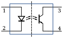
An opto-isolator contains a source (emitter) of light, almost always a near infrared light-emitting diode (LED), that converts electrical input signal into light, a closed optical channel (also called dielectrical channel[5]), and a photosensor, which detects incoming light and either generates electric energy directly, or modulates electric current flowing from an external power supply. The sensor can be a photoresistor, a photodiode, a phototransistor, a silicon-controlled rectifier (SCR) or a triac. Because LEDs can sense light in addition to emitting it, construction of symmetrical, bidirectional opto-isolators is possible. An optocoupled solid state relay contains a photodiode opto-isolator which drives a power switch, usually a complementary pair of MOSFET transistors. A slotted optical switch contains a source of light and a sensor, but its optical channel is open, allowing modulation of light by external objects obstructing the path of light or reflecting light into the sensor.
Photoresistor-based opto-isolators were introduced in the 1960s. They are the slowest, but also the most linear isolators and still retain a niche market in audio and music industry. Commercialization of LED technology in 1968–1970 caused a boom in optoelectronics, and by the end of the 1970s the industry developed all principal types of opto-isolators. The majority of opto-isolators on the market use bipolar silicon phototransistor sensors.[6] They attain medium data transfer speed, sufficient for applications like electroencephalography.[7] The fastest opto-isolators use PIN diodes in photoconductive mode and contain electronic circuitry for amplification, shaping and interfacing of the signal detected by the sensor, and can attain data transfer rates of 50 MBd.[8] Their role in computing and communications is being challenged by new integrated isolation devices based on microminiature transformers, capacitive coupling or spin valves.
Contents[hide] |
[edit] Electric isolation

The main function of an opto-isolator is to block such high voltages and voltage transients, so that a surge in one part of the system will not disrupt or destroy the other parts.[2] Or, according to the authors of The Art of Electronics, "in a nutshell, opto-couplers let you send digital (and sometimes analog) signals between circuits with separate grounds."[12] Historically, this function was delegated to isolation transformers, which use inductive coupling between galvanically isolated input and output sides. Transformers and opto-isolators are the only two classes of electronic devices that offer reinforced protection — they protect both the equipment and the human user operating this equipment.[13] They contain a single physical isolation barrier, but provide protection equivalent to double isolation.[13] Safety, testing and approval of opto-couplers are regulated by national and international standards: IEC 60747-5-2, EN (CENELEC) 60747-5-2, UL 1577, CSA Component Acceptance Notice #5, etc.[14] Opto-isolator specifications published by manufacturers always follow at least one of these regulatory frameworks.
An opto-isolator connects input and output sides with a beam of light modulated by input current. It transforms useful input signal into light, sends it across the dielectric channel, captures light on the output side and transforms it back into electric signal. Unlike transformers, which pass energy in both directions[note 3] with very low losses, opto-isolators are unidirectional (see exceptions) and they cannot transmit power.[15] Typical opto-isolators can only modulate the flow of energy already present on the output side.[15] Unlike transformers, opto-isolators can pass DC or slow-moving signals and do not require matching impedances between input and output sides.[note 4] Both transformers and opto-isolators are effective in breaking ground loops, common in industrial and stage equipment, caused by high or noisy return currents in ground wires.[16]
The physical layout of an opto-isolator depends primarily on the desired isolation voltage. Devices rated for less than a few kV have planar (or sandwich) construction.[17] The sensor die is mounted directly on the lead frame of its package (usually, a six-pin or a four-pin dual in-line package).[5] The sensor is covered with a sheet of glass or clear plastic, which is topped with the LED die.[5] The LED beam fires downward. To minimize losses of light, the useful absorption spectrum of the sensor must match the output spectrum of the LED, which almost invariably lies in the near infrared.[18] The optical channel is made as thin as possible for a desired breakdown voltage.[17] For example, to be rated for short-term voltages of 3.75 kV and transients of 1 kV/μs, the clear polyimide sheet in the Avago ASSR-300 series is only 0.08 mm thick.[19] Breakdown voltages of planar assemblies depend on the thickness of the transparent sheet[17] and the configuration of bonding wires that connect the dies with external pins.[5] Real in-circuit isolation voltage is further reduced by creepage over the PCB and the surface of the package. Safe design rules require a minimal clearance of 25 mm/kV for bare metal conductors or 8.3 mm/kV for coated conductors.[20]
Opto-isolators rated for 2.5 to 6 kV employ a different layout called silicone (sic) dome.[21] Here, the LED and sensor dies are placed on the opposite sides of the package; the LED fires into the sensor horizontally.[21] The LED, the sensor and the gap between them are encapsulated in a blob, or dome, of transparent silicone. The dome acts as a reflector, retaining all stray light and reflecting it onto the surface of the sensor, minimizing losses in a relatively long optical channel.[21] In double mold designs the space between the silicone blob ("inner mold") and the outer shell ("outer mold") is filled with dark dielectric compound with a matched coefficient of thermal expansion.[22]
[edit] Types of opto-isolators
| Device type[note 5] | Source of light[5] | Sensor type[5] | Speed | Current transfer ratio |
|---|---|---|---|---|
| Resistive opto-isolator (Vactrol) | Incandescent light bulb | CdS or CdSe photoresistor (LDR) | Very low | <100%[note 6] |
| Neon lamp | Low | |||
| GaAs infrared LED | Low | |||
| Diode opto-isolator | GaAs infrared LED | Silicon photodiode | Highest | 0.1% - 0.2%[23] |
| Transistor opto-isolator | GaAs infrared LED | Bipolar silicon phototransistor | Medium | 2% - 120%[23] |
| Darlington phototransistor | Medium | 100% - 600%[23] | ||
| Opto-isolated SCR | GaAs infrared LED | Silicon-controlled rectifier | Low to medium | >100%[24] |
| Opto-isolated triac | GaAs infrared LED | TRIAC | Low to medium | Very high |
| Opto-isolated maus | DoNs infrared LED | TRIAC | Low to high | Extremely high |
| Solid-state relay | Stack of GaAs infrared LEDs | Stack of photodiodes driving a pair of MOSFETs or an IGBT | Low to high[note 7] | Practically unlimited |
[edit] Resistive opto-isolators
The earliest opto-isolators, originally marketed as light cells, emerged in the 1960s. They employed miniature incandescent light bulbs as sources of light, and cadmium sulfide (CdS) or cadmium selenide (CdSe) photoresistors (also called light-dependent resistors, LDRs) as receivers. In applications where control linearity was not important, or where available current was too low for driving an incandescent bulb (as was the case in vacuum tube amplifiers), it was replaced with a neon lamp. These devices (or just their LDR component) were commonly named Vactrols, after a trademark of Vactec, Inc. The trademark has since been genericized,[note 8] but the original Vactrols are still being manufactured by PerkinElmer.[25][note 9]The turn-on and turn-off lag of an incandescent bulb lies in hundreds of milliseconds range, which makes the bulb an effective low-pass filter and rectifier but limits the practical modulation frequency range to a few Hertz. With the introduction of light-emitting diodes (LEDs) in 1968–1970,[26] the manufacturers replaced incandescent and neon lamps with LEDs and achieved response times of 5 milliseconds and modulation frequencies up to 250 Hz.[27] The name Vactrol was carried over on LED-based devices which are, as of 2010, still produced in small quantities.[28]
Photoresistors used in opto-isolators rely on bulk effects in a uniform film of semiconductor; there are no p-n junctions.[29] Uniquely among photosensors, photoresistors are non-polar devices suited for either AC or DC circuits.[29] Their resistance drops in reverse proportion to the intensity of incoming light, from virtually infinity to a residual floor that may be as low as less than a hundred Ohms.[29] These properties made the original Vactrol a convenient and cheap automatic gain control and compressor for telephone networks. The photoresistors easily withstood voltages up to 400 Volts,[29] which made them ideal for driving vacuum fluorescent displays. Other industrial applications included photocopiers, industrial automation, professional light measurement instruments and auto-exposure meters.[29] Most of these applications are now obsolete, but resistive opto-isolators retained a niche in audio, in particular guitar amplifier, markets.
American guitar and organ manufacturers of the 1960s embraced the resistive opto-isolator as a convenient and cheap tremolo modulator. Fender's early tremolo effects used two vacuum tubes; after 1964 one of these tubes was replaced by an optocoupler made of a LDR and a neon lamp.[30] To date, Vactrols activated by pressing the stompbox pedal are ubiquitous in the music industry.[31] Shortages of genuine PerkinElmer Vactrols forced the DIY guitar community to "roll their own" resistive opto-isolators.[32] Guitarists to date prefer opto-isolated effects because their superior separation of audio and control grounds results in "inherently high quality of the sound".[32] However, the distortion introduced by a photoresistor at line level signal is higher than that of a professional electrically-coupled voltage-controlled amplifier.[33] Performance is further compromised by slow fluctuations of resistance owing to light history, a memory effect inherent in cadmium compounds. Such fluctuations take hours to settle and can be only partially offset with feedback in the control circuit.[34]
[edit] Photodiode opto-isolators
Diode opto-isolators employ LEDs as sources of light and silicon photodiodes as sensors. When the photodiode is reverse-biased with an external voltage source, incoming light increases the reverse current flowing through the diode. The diode itself does not generate energy; it modulates the flow of energy from an external source. This mode of operation is called photoconductive mode. Alternatively, in the absence of external bias the diode converts the energy of light into electric energy by charging its terminals to a voltage of up to 0.7 V. The rate of charge is proportional to the intensity of incoming light. The energy is harvested by draining the charge through an external high-impedance path; the ratio of current transfer can reach 0.2%.[23] This mode of operation is called photovoltaic mode.The fastest opto-isolators employ PIN diodes in photoconductive mode. The response times of PIN diodes lie in the subnanosecond range; overall system speed is limited by delays in LED output and in biasing circuitry. To minimize these delays, fast digital opto-isolators contain their own LED drivers and output amplifiers optimized for speed. These devices are called full logic opto-isolators: their LEDs and sensors are fully encapsulated within a digital logic circuit.[35] The Hewlett-Packard 6N137/HPCL2601 family of devices equipped with internal output amplifiers was introduced in the late 1970s and attained 10 MBd data transfer speeds.[36] It remained an industry standard until the introduction of the 50 MBd Agilent Technologies[note 10] 7723/0723 family in 2002.[8] The 7723/0723 series opto-isolators contain CMOS LED drivers and a CMOS buffered amplifiers, which require two independent external power supplies of 5 V each.[37]
Photodiode opto-isolators can be used for interfacing analog signals, although their non-linearity invariably distorts the signal. A special class of analog opto-isolators introduced by Burr-Brown uses two photodiodes and an input-side operational amplifier to compensate for diode non-linearity. One of two identical diodes is wired into the feedback loop of the amplifier, which maintains overall current transfer ratio at a constant level regardless of the non-linearity in the second (output) diode.[38]
Solid-state relays built around MOSFET switches usually employ a photodiode opto-isolator to drive the switch. The gate of a MOSFET requires relatively small total charge to turn on and its leakage current in steady state is very low. A photodiode in photovoltaic mode can generate turn-on charge in a reasonably short time but it's output voltage is many times less than the MOSFET's threshold voltage. To reach the required threshold, solid-state relays contain stacks of up to thirty photodiodes wired in series.[22]
[edit] Phototransistor opto-isolators
Phototransistors are inherently slower than photodiodes.[39] The earliest and the slowest but still common 4N35 opto-isolator, for example, has rise and fall times of 5 μs into a 100 Ohm load[40] and its bandwidth is limited at around 10 kiloHertz - sufficient for applications like electroencephalography[7] or pulse-width motor control.[41] Devices like PC-900 or 6N138 recommended in the original 1983 Musical Instrument Digital Interface specification[42] allow digital data transfer speeds of tens of kiloBauds.[43] Phototransistors must be properly biased and loaded to achieve their maximum speeds, for example, the 4N28 operates at up to 50 kHz with optimum bias and less than 4 kHz without it.[44]Design with transistor opto-isolators requires generous allowances for wide fluctuations of parameters found in commercially available devices.[44] Such fluctuations may be destructive, for example, when an opto-isolator in the feedback loop of a DC-to-DC converter changes its transfer function and causes spurious oscillations,[21] or when unexpected delays in opto-isolators cause a short circuit through one side of an H-bridge.[45] Manufacturers' datasheets typically list only worst-case values for critical parameters; actual devices surpass these worst-case estimates in an unpredictable fashion.[44] Bob Pease observed that current transfer ratio in a batch of 4N28's can vary from 15% to more than 100%; the datasheet specified only a minimum of 10%. Transistor beta in the same batch can vary from 300 to 3000, resulting in 10:1 variance in bandwidth.[44]
Opto-isolators using field-effect transistors (FETs) as sensors are rare and, like vactrols, can be used as remote-controlled analog potentiometers provided that the voltage across the FET's output terminal does not exceed a few hundred mV.[38] Opto-FETs turn on without injecting switching charge in the output circuit, which is particularly useful in sample and hold circuits.[12]
[edit] Bidirectional opto-isolators
All opto-isolators described so far are uni-directional. Optical channel always works one way, from the source (LED) to the sensor. The sensors, be it photoresistors, photodiodes or phototransistors, cannot emit light.[note 11] But LEDs, like all semiconductor diodes,[note 12] are capable of detecting incoming light, which makes possible construction of a two-way opto-isolator from a pair of LEDs. The simplest bidirectional opto-isolator is merely a pair of LEDs placed face to face and held together with heat-shrink tubing. If necessary, the gap between two LEDs can be extended with a glass fiber insert.[46]Visible spectrum LEDs have relatively poor transfer efficiency, thus near infrared spectrum GaAs, GaAs:Si and AlGaAs:Si LEDs are the preferred choice for bidirectional devices. Bidirectional opto-isolators built around pairs of GaAs:Si LEDs have current transfer ratio of around 0.06% in either photovoltaic or photoconductive mode — less than photodiode-based isolators,[47] but sufficiently practical for real-world applications.[46]
[edit] Alternatives
- In 2000 Analog Devices introduced integrated magnetic isolators — electrically-decoupled 100 MBit/s, 2.5 kV isolation circuits employing air core transformers micromachined on the surface of silicon integrated circuits. They featured lesser power consumption, lesser cost[note 13] and were four times faster than the fastest contemporary opto-isolators.[49] In 2010, Analog increased the speed of their magnetic isolators to 150 MBit/s and offered isolation up to 5 kV.[50] Microtransformer-based isolators can work as dc-dc converters, passing both signal and power. Commercially available ICs can carry up to four isolated digital channels and a 2 W isolated power channel in miniature 20-pin packages.[51] According to Analog Devices, by October 2010 the company has more "than 450 million [magnetic isolator] channels deployed".[51] In the same year NEC and Renesas announced transformer-based CMOS devices with transfer rates of 250 MBit/s.[52][53]
- High-speed capacitive-coupled isolators[note 14] were introduced in 2000 by Silicon Laboratories and commercialized by Texas Instruments. These devices convert an incoming data stream into an amplitude-modulated UHF signal, pass it through a silicon dioxide isolation layer, and demodulate the received signal. The spectra of spurious voltage transients, which can pass through the capacitive barrier and disrupt operation, lie far below the modulation frequency and can be effectively blocked. As of 2010, capacitive-coupled isolators offer data transfer speeds of 150 MBit/s and voltage isolation of 560 V continuous and 4 kV peak across the barrier.[54]
- NVE Corporation, the pioneer of magnetoresistive random access memory, markets an alternative type of isolator based on giant magnetoresistance (GMR) effect (Spintronic and IsoLoop trademarks). Each isolation cell of these devices is formed by a flat square coil which is micromachined above four spin valve sensors buried in the silicon wafer.[55] These sensors, wired into a Wheatstone bridge circuit, generate binary on/off output signals.[56] At the time of their introduction in 2002, NVE advertised speeds 5 to 10 times higher than the fastest opto-isolators;[55] and in March 2008 commercial devices marketed by NVE were rated for speeds up to 150 MBit/s.[56]


